Sany SY365CC Excavator E System Principle
The Sany Parts Sany SY365CC Excavator E System Principle is the complete electrical control architecture for the SY365CC excavator. It integrates power distribution, control modules, and operator interface components. This this pipeline includes the main controller, display unit, wiring harnesses, and all associated switches and relays. It provides the electronic intelligence for all machine functions. The Sany hydraulic controller at the heart of the Sany SY365CC Excavator E System Principle manages engine speed, pump output, and hydraulic valve actuation. It ensures optimal coordination of all machine systems.
Comprehensive fuse protection in the Sany SY365CC Excavator E System Principle safeguards all circuits from overload damage. Individual fuses for each subsystem allow quick diagnosis of electrical faults. As a genuine Sany component set, the Sany SY365CC Excavator E System Principle is backed by comprehensive warranty. The electrical system is designed for reliable operation in harsh mining environments. The this device is trusted by operators worldwide for consistent performance in demanding excavation environments. Every component meets rigorous factory standards. Regular maintenance of the this equipment helps prevent unexpected downtime on the job site. Operators should follow the recommended inspection schedule for optimal service life.
Using genuine Sany parts for the this product ensures proper fit and function within the excavator system. Aftermarket alternatives may not meet the same performance specifications.
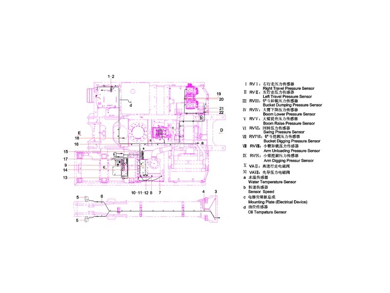
Sany SY365CC Excavator E System Principle
What is the Sany SY365CC Excavator E System Principle?
The this system is the master electrical control framework that governs all electronic functions on the excavator. It connects the operator commands to the machine’s hydraulic and engine systems.
This this component features a configurable hydraulic controller that can be programmed for specific machine applications. The controller pinboard provides interface connectivity for sensors and actuators.
Multiple intermediate relays in the this assembly handle high-current switching for solenoids and motors. These relays isolate the controller from electrical loads for protection.
The Sany display unit in the this module provides real-time machine status information to the operator. Fuel level, engine temperature, and system warnings are displayed clearly.
Work lamps and LED indicators in the this mechanism provide visual status feedback. Red and yellow indicator lamps alert operators to system warnings and critical alarms.
Harness clamps and wire clips throughout the this filter secure wiring harnesses along the chassis. Proper routing prevents chafing and electrical shorts in the vibrating environment.
The ignition switch and fuel control switch in the this pump provide operator control over engine start and shutdown. These switches are rated for the demanding excavator duty cycle.
Sany has designed the this motor with a fused power distribution architecture. Individual circuit protection allows technicians to isolate and diagnose electrical faults quickly.
The this configuration is engineered with precision manufacturing techniques that ensure dimensional accuracy and consistent quality across all production batches.
Advanced materials used in the this setup provide superior resistance to wear and fatigue under heavy loads. The material selection considers demanding excavator operating conditions.
The this valve assembly is designed for straightforward installation on the SY365CC excavator platform. All mounting points match the original equipment specifications precisely.
Quality control for the this pipeline includes multiple inspection stages throughout the manufacturing process. This systematic approach ensures consistent component quality.
The Sany SY365CC Excavator E System Principle benefits from continuous product improvement based on field performance data. Engineering updates enhance durability and service life.
Product Parameters of Sany SY365CC Excavator E System Principle
| Index | Parts Number | Parts Name |
|---|---|---|
| 1 | 11953235 | Switch, oil feed pump shutdown |
| 2 | 11953236 | Switch, oil feed pump startup |
| 3 | A230200000021 | PVC tape |
| 4 | B241000000022 | Post, binding |
| 5 | 12677339 | Lamp, working |
| 6 | A820202010674 | Clamp, harness |
| 7 | 60012805 | Wire, power supply |
| 8 | 60197055 | Wire, power supply |
| 9 | 60012803 | Battery |
| 10 | 60012806 | Wire, power supply |
| 11 | 60012807 | Connector GP, battery positive |
| 12 | 60012810 | Connector GP, battery negative |
| 13 | A210111000200 | Bolt M6x20GB5783 |
| 14 | 60197016 | Socket |
| 15 | A820202010383 | Clamp, harness |
| 16 | A820202010075 | Clamp, harness |
| 17 | A820202010386 | Retainer, harness |
| 18 | A820202010588 | Clip, harness |
| 19 | A820202010589 | Bracket, harness |
| 20 | A820202010587 | Strap, nylon |
| 21 | 11768685 | Frame, fixing, wire clip |
| 22 | 60086357 | Clamp, harness |
| 23 | A210210000027 | Screw M8x16GB818 |
| 24 | A210401000018 | Washer 8GB96.1 |
| 25 | 12772933 | Harness, chassis |
| 26 | A820202010383 | Clamp, harness |
| 27 | A820202010385 | Clamp, harness |
| 28 | 60086356 | Clamp, harness |
| 29 | A210111000258 | Bolt M12x20GB5783 10.9 |
| 30 | A210401000002 | Washer 12GB97.1 |
| 31 | B240700000250 | Fuse |
| 32 | B240700000251 | Fuse |
| 33 | A210111000199 | Bolt M10x20GB5783 10.9 |
| 34 | A210401000001 | Washer 10GB97.1 |
| 35 | 60023703 | Radio |
| 36 | 60090606 | Horn |
| 37 | 12762529 | Work lamp |
| 38 | 12772930 | Display, control |
| 39 | 12772935 | Harness, cab |
| 40 | B240100000932 | LED indicator lamp, red |
| 41 | B240100000546 | LED indicator lamp, yellow |
| 42 | A240200000010 | Switch, ignition |
| 43 | A240200000011 | Switch, fuel control |
| 44 | A210111000199 | Bolt M10x20GB5783 10.9 |
| 45 | A210401000001 | Washer 10GB97.1 |
| 46 | A210111000053 | Bolt M14x40GB5783 10.9 |
| 47 | A210405000005 | Washer 14GB97.1 |
| 48 | A210307000005 | Nut M20GB6170 |
| 49 | 12772931 | Harness, control switch |
| 50 | 12772935 | Fuse box harness |
| 51 | A210111000206 | Bolt M12x30GB5783 10.9 |
| 52 | A210405000004 | Washer 12GB97.1 |
| 53 | 12772932 | Harness, fuse box |
Why Choose Our Sany SY365CC Excavator E System Principle?
Genuine OEM Quality
Every Sany SY365CC Excavator E System Principle component is manufactured to original factory specifications with strict quality control standards.
Fast Global Shipping
We maintain ample stock of the Sany SY365CC Excavator E System Principle components for immediate dispatch to customers worldwide.
Competitive Pricing
Our this device components offer exceptional value with direct-from-manufacturer pricing.
Expert Technical Support
Professional technical assistance is available for the this equipment installation and troubleshooting.
Our this product is backed by comprehensive warranty coverage that protects your investment. We stand behind the quality of every component we supply.
Customers choose our this system for the combination of OEM quality and competitive pricing. We deliver genuine performance without dealer premium pricing.
What are the Routine Maintenance Considerations for the Sany SY365CC Excavator E System Principle?
Inspect all wiring harnesses in the this component for chafing or damage monthly. Exposed wires can cause short circuits and intermittent electrical faults that are difficult to diagnose.
Check fuse ratings in the this assembly when replacing blown fuses. Always use the correct amperage fuse as specified to prevent wiring damage and potential fire hazards.
Keep the controller connectors in the Sany SY365CC Excavator E System Principle clean and dry. Moisture and dirt in electrical connectors cause corrosion and poor signal transmission between control modules.
Test the battery connections in the Sany SY365CC Excavator E System Principle for tightness and corrosion during routine service. Poor battery connections cause starting problems and voltage fluctuations.
Inspect the Sany SY365CC Excavator E System Principle at regular intervals according to the excavator maintenance schedule. Early detection of wear prevents more extensive repairs and costly downtime.
Keep the Sany SY365CC Excavator E System Principle clean and free from debris accumulation during operation. Contaminants can accelerate component wear and compromise sealing surfaces.
Document all maintenance activities performed on the Sany SY365CC Excavator E System Principle in the machine service log. Accurate records help track service intervals and identify recurring issues.
Use only approved lubricants and fluids when servicing the Sany SY365CC Excavator E System Principle. Incorrect products can damage seals and internal components, leading to premature failure.
Replace the Sany SY365CC Excavator E System Principle promptly if inspection reveals cracks, excessive wear, or deformation. Operating with damaged components risks further damage to connected systems.
Online Catalog of SANY Parts
Learn MoreIf you have any questions about our products, services, or anything related to what we offer, please don’t hesitate to leave us a message—our dedicated team is always ready to provide prompt and helpful responses to address your concerns. What’s more, when you become our valued customer, we’re delighted to offer you complimentary catalog services, giving you access to detailed, up-to-date information on our full range of products, specifications, and offerings to help you make informed decisions.