OEM 168899003946A Valve Guide – Genuine SANY Cylinder Head Alignment Component
168899003946A
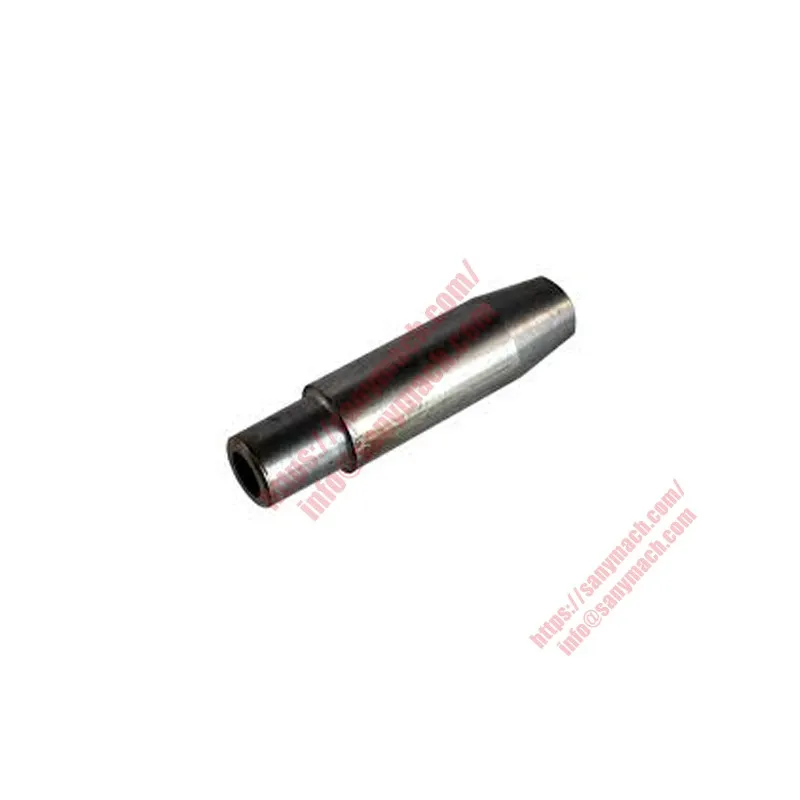
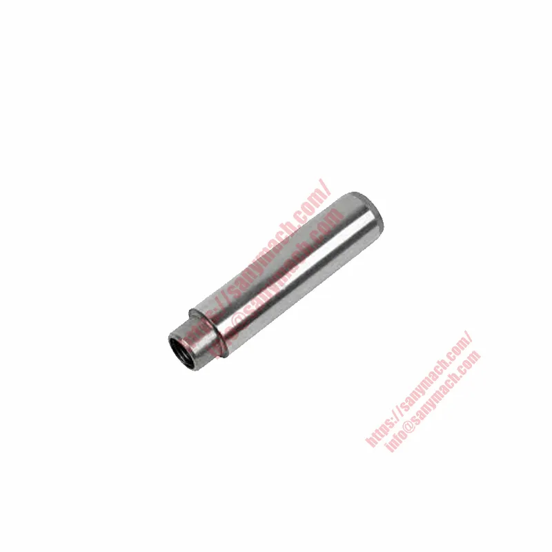
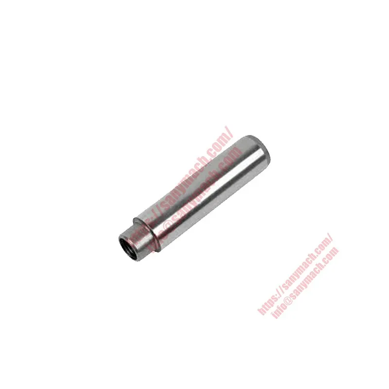
Valve Guide
Руководство по клапанам
Guía de válvulas
The genuine SANY parts reference 168899003946A is the Valve Guide, a precision-machined cylindrical component that provides the critical bearing surface for valve stem movement within the cylinder head of SANY heavy-duty diesel engines. This valve guide ensures that intake and exhaust valves open and close with perfect axial alignment, maintaining optimal combustion sealing, consistent valve motion, and controlled oil consumption. The 168899003946A valve guide is manufactured from high-strength wear-resistant powder metal or bronze alloy material, delivering exceptional friction properties, thermal conductivity, and dimensional stability under peak cylinder pressures exceeding 200 bar.
As an integral component of the SANY Cylinder Head Subassembly (160102130004A094), four units of the 168899003946A Valve Guide are installed per cylinder head – two for intake valves and two for exhaust valves – with a total of 24 guides per complete 6-cylinder D09 or D12 engine [5†L23-L26][7†L4-L7]. Each 168899003946A guide is precision-reamed to tight tolerances and press-fitted into the cylinder head casting, ensuring perfect concentricity with the corresponding valve seat [5†L9-L10]. Each 168899003946A unit is 100% inspected for inner diameter accuracy, outer diameter roundness, and surface finish, guaranteeing reliable performance in SRT dump trucks, SY excavators, SW wheel loaders, and motor graders operating in the most demanding mining, construction, and material handling environments.
Integration Within the SANY Cylinder Head Subassembly
The valve guide 168899003946A is a fundamental component of the SANY Cylinder Head Subassembly (160102130004A094), which forms the structural foundation for the engine’s top end. According to the SANY Cylinder Head Subassembly catalog, four units of the 168899003946A Valve Guide are installed per cylinder head, working in conjunction with the Cylinder Head (160102130004A098), Exhaust Valve Seat (160102130004A099), and Intake Valve Seat (160102130004A012) to form a complete valve operating system [5†L23-L26][7†L4-L7]. The valve guide is press-fitted into a precision-machined bore in the cylinder head, providing a permanent, rotation-resistant mounting that maintains perfect concentricity with the valve seat.
Within the SANY Cylinder Head Subassembly, the 168899003946A valve guide works synergistically with several other critical components. The guide is sealed at its upper end by the Valve Stem Seal (60141426 or 61000113), which controls oil flow onto the valve stem while preventing excess oil from entering the combustion chamber. The Intake Valve Seat (160102130004A012) and Exhaust Valve Seat (160102130004A099) are pressed into the cylinder head casting below the valve guide, providing a hardened, wear-resistant surface for the valve head to seal against [5†L26-L30]. The push rod bush (160102130004A013) and various plug components (60352172, 60352173, 61000101) complete the subassembly, ensuring perfect alignment of the entire valve train [5†L28-L30].
The 168899003946A valve guide is specifically designed for use in SANY D09 and D12 series diesel engines. The D09 engine is a straight-6 diesel with a displacement of 8.7 liters, featuring a bore of 117 mm and a stroke of 135 mm, producing between 280 and 380 horsepower with a maximum torque of 1,500 N·m at 1,000-1,500 rpm. The D12 engine offers even greater displacement and power output, with a bore of 131 mm and a stroke of 150 mm, resulting in a total displacement of 12.13 liters and output torque reaching 700 N·m with idle speeds down to 525 rpm. Both engine families utilize a split-type cylinder head design adopted to minimize engine noise while enabling efficient cooling through SANY’s patented TOP-Down cooling system, which quickly reduces the temperature of the circulating fluid to improve engine efficiency.
Design and Function of Valve Guide 168899003946A
The valve guide 168899003946A serves three essential functions within the engine. First, it provides accurate axial positioning for the valve stem, ensuring that the valve head contacts the valve seat squarely and consistently, which is critical for maintaining compression and preventing combustion gas leakage. Second, the guide acts as a heat transfer path, conducting heat away from the valve stem and into the cylinder head’s cooling system, preventing valve overheating and potential warping or burning. Third, the guide works in conjunction with the valve stem seal to meter the correct amount of engine oil onto the valve stem, providing lubrication while preventing excess oil from entering the combustion chamber.
The 168899003946A valve guide is manufactured from high-strength wear-resistant powder metal or bronze alloy material, specifically formulated to provide excellent friction properties, thermal conductivity, and dimensional stability under extreme operating conditions. The guide’s inner diameter is precision-reamed to achieve a tight tolerance fit with the valve stem, typically producing a clearance of 0.03-0.05 mm for intake valves and 0.05-0.07 mm for exhaust valves. This controlled clearance allows the valve stem to slide freely while minimizing oil passage and preventing combustion gas blow-by. The outer diameter of the guide is finished to a press-fit tolerance, ensuring a secure, permanent mounting in the cylinder head when installed.
The 168899003946A valve guide features a precisely machined upper counterbore that accepts the valve stem seal, creating a secure seat for the elastomeric seal. The guide’s top surface is finished flat and square to the axis, providing a consistent mounting surface for the valve spring seat or retainer. Some engine variants may include an additional groove machined into the outer diameter of the guide for a retaining snap ring, which prevents the guide from moving upward in the cylinder head under extreme operating conditions. The overall length of the guide is engine-specific, designed to provide adequate bearing surface for the valve stem while positioning the valve seal at the correct height above the cylinder head deck.
All 168899003946A valve guides are 100% inspected for inner diameter accuracy using air gauges, outer diameter roundness using precision micrometers, and overall length using electronic height gauges. A sample from each production batch is sectioned for metallographic examination to verify material density, porosity, and microstructure. Hardness testing (Rockwell HRB or equivalent) is performed to confirm that the guide meets the material specification for wear resistance. Each guide is visually inspected for surface defects, cracks, or dimensional irregularities before packaging.
Valve Train Integration and Component Relationships
The valve guide 168899003946A is a critical element of the complete SANY valve train system, which includes the cylinder head, valves, valve seats, valve springs, retainers, and valve stem seals. The intake and exhaust valves are inserted through the guide from the combustion chamber side, passing through the guide bore before being secured by valve springs and retainers on the top side of the cylinder head. When the valve opens, the valve stem slides upward through the guide, compressing the valve spring. When the valve closes, the spring forces the valve stem back down through the guide, seating the valve head against the valve seat.
The clearance between the valve stem and the 168899003946A guide is carefully controlled to optimize oil consumption and engine performance. Insufficient clearance can cause the valve stem to bind in the guide, leading to sticking valves, loss of compression, and potential piston-to-valve contact. Excessive clearance allows too much oil to enter the combustion chamber, causing blue exhaust smoke, carbon buildup on valve faces, and increased emissions. The valve stem seal, installed over the top of the guide, controls the flow of oil onto the stem, ensuring that just enough oil reaches the guide interface for lubrication without flooding the combustion chamber. The sophisticated engineering of the SANY valve train ensures minimal friction, consistent valve timing, and extended service life in the most demanding applications [3†L12-L15][5†L9-L11].
During the engine rebuild process, after new valve guides are installed, the valve seats must be re-cut to ensure perfect concentricity with the guides. This is typically done using a valve seat cutting tool that pilots off the guide bore, guaranteeing that the seat is precisely aligned with the guide. If the guide and seat are not concentric, the valve will not seat properly, leading to compression loss, valve burning, and reduced engine performance. The 168899003946A guide is designed to accept standard valve guide reamers and cutting tools, allowing engine rebuilders to restore proper clearances when reconditioning used cylinder heads.
Technical Specifications – Valve Guide 168899003946A
| Parameter | Specification / Value |
|---|---|
| OEM Part Number | 168899003946A |
| Product Name | Valve Guide |
| Material | High-strength wear-resistant powder metal or bronze alloy |
| Quantity per Cylinder Head | 4 (two intake + two exhaust) |
| Quantity per Engine (6-cylinder) | 24 (4 guides × 6 cylinder heads) |
| Manufacturing Process | Powder metal sintering or precision casting + machining + reaming |
| Inner Diameter Tolerance | H7 (precision-reamed for exact valve stem fit) |
| Outer Diameter Fit | Press-fit interference fit in cylinder head bore |
| Surface Finish (ID) | Ra ≤ 0.8 µm (precision-reamed) |
| Surface Finish (OD) | Ra ≤ 1.6 µm (ground for press-fit) |
| Cylinder Head Subassembly | 160102130004A094 |
| Intake Valve Seat | 160102130004A012 |
| Exhaust Valve Seat | 160102130004A099 |
| Valve Stem Seals (Compatible) | 60141426 and 61000113 |
| Cylinder Head | 160102130004A098 |
Symptoms of Worn or Failed Valve Guides
Worn valve guides, including the 168899003946A, can produce several characteristic symptoms that equipment operators and technicians should recognize. Blue exhaust smoke that appears during startup or after extended idle periods is a common indicator of worn valve guides. When the engine idles, high manifold vacuum draws oil past worn guides and into the combustion chamber, where it burns and produces blue smoke upon acceleration. This symptom is often most noticeable after the engine has been sitting at idle for a minute or more, followed by a cloud of blue smoke when the throttle is opened.
Excessive oil consumption without visible external leaks may also indicate worn valve guides. As the guide bore wears, the clearance between the valve stem and guide increases, allowing more oil to flow past the valve stem seal and into the combustion chamber. Carbon buildup on valve stems, valve faces, and piston crowns can also result from worn guides, leading to reduced performance, increased emissions, and hot spots that may cause pre-ignition or valve burning. A cylinder leak-down test can help distinguish valve guide wear from piston ring wear — if compressed air escapes past the valve area when the cylinder is pressurized, valve guide or valve sealing issues are indicated.
If the engine exhibits these symptoms, the valve guides should be inspected during the next cylinder head overhaul. To check valve guide-to-valve stem clearance, thoroughly clean the valve guide and, using a split-ball gauge, measure the inside diameter of the guide. Compare this measurement to the measured diameter of the valve stem. The maximum allowable wear on valve guides varies by engine application, but the general service limit for intake valve guide I.D. is 7.134 mm while 7.159 mm for exhaust guides [3†L18-L20]. If the guide-to-stem clearance exceeds the service limit, the guide must be replaced.
Proper Installation of Valve Guide 168899003946A
When installing the valve guide 168899003946A, absolute cleanliness and precise technique are essential for achieving proper alignment and retention. Before installation, thoroughly clean the valve guide bore in the cylinder head using a lint-free cloth and degreasing solvent, removing all carbon deposits, old sealant residue, or debris. Inspect the cylinder head for cracks around the guide bore area — if any damage is present, the cylinder head must be repaired or replaced before new guides are installed.
The 168899003946A guide is installed by pressing it into the cylinder head bore using a suitable installation tool and an arbor press. Apply a thin film of clean engine oil to the outer diameter of the guide to facilitate installation. The guide must be pressed straight into the bore without tilting — any tilt will result in a misaligned guide that will cause valve stem binding and rapid wear. The guide should be pressed until it is seated to the specified height above the cylinder head deck (typically 12-18 mm, engine-specific). Never hammer the guide into place, as shock loading can damage the guide or the cylinder head bore.
After installation, verify the guide-to-valve stem clearance using a valve stem and a dial bore gauge or split-ball gauge. The clearance should be within the manufacturer’s specification — typically 0.03-0.05 mm for intake valves and 0.05-0.07 mm for exhaust valves for heavy-duty diesel engines. If the clearance is too tight, the guide must be reamed to the correct size using a precision valve guide reamer. If the clearance is too loose, the guide must be removed and replaced with a new guide — do not attempt to knurl or resize guides with excessive wear. After the guides are installed and the correct clearance is verified, the valve seats should be cut or ground to ensure perfect concentricity with the new guides [3†L12-L15].
Always replace the valve stem seals (60141426 or 61000113) whenever the valve guides are replaced. The elastomeric seals can be damaged during guide installation, and even if they appear undamaged, they should be replaced as part of the cylinder head overhaul process. After the cylinder head is reassembled and installed on the engine, perform a compression test or cylinder leak-down test to verify that the valves are seating correctly and that no combustion gas leakage is occurring past the new guides and seals.
Quality Assurance & Full Traceability
Every valve guide 168899003946A is manufactured in an IATF 16949 certified facility under SANY’s rigorous quality management system. The production process includes raw material verification, in-process dimensional inspection using precision air gauges and micrometers, and 100% visual and automated inspection of critical features including inner diameter, outer diameter, overall length, and surface finish. A sample from each production batch is sectioned for metallographic examination to verify material density, porosity, and microstructure.
The inner diameter of the 168899003946A guide is measured to an accuracy of ±0.002 mm to ensure the precise H7 tolerance required for correct valve stem fitment. The outer diameter is verified for press-fit interference, and the concentricity between the inner and outer diameters is checked using precision indicators. The guide’s top counterbore diameter and depth are inspected for proper valve stem seal seating. A sample from each batch is subjected to hardness testing to confirm that the guide meets the material specification for wear resistance.
Each 168899003946A valve guide is packaged in protective packaging that prevents contamination and damage during storage and transport. The packaging is labeled with the SANY logo, part number, quantity (4 per package for a complete cylinder head set), and a batch code that links to the original manufacturing records, including the raw material certificate, sintering or casting parameters, machining records, and final inspection data [5†L23-L26][7†L4-L7]. For bulk orders, a Certificate of Conformance (CoC) is provided, certifying that the guides meet all SANY OEM specifications for material composition, dimensional accuracy, hardness, and surface finish.
Field Performance of Genuine SANY Valve Guides
Field data collected from SANY dump trucks and excavators operating in Australian iron ore mines and South African quarries shows that genuine 168899003946A valve guides maintain proper stem clearance and sealing integrity for the full engine service interval, typically exceeding 20,000 operating hours. Aftermarket guides often fail prematurely due to inferior material quality, incorrect dimensional tolerances, or insufficient wear resistance, leading to valve guide wear, excessive oil consumption, and blue smoke within 8,000-12,000 hours.
The superior durability of the genuine SANY valve guide comes from the premium powder metal or bronze alloy material, the precisely controlled sintering or casting process that ensures consistent density, and the precision-reamed inner diameter that maintains proper valve stem clearance over thousands of thermal cycles. Fleet owners report that standardizing on genuine SANY valve guides reduces oil consumption by up to 50% and eliminates valve stem seizure issues caused by guide distortion or poor material quality [5†L9-L11]. The precise alignment of the 168899003946A guides also contributes to longer valve seat life, as the concentric relationship between the guide and seat prevents valve head wobble and uneven seat wear.
To maximize service life, always replace valve guides when overhauling an engine that has exhibited high oil consumption or blue smoke symptoms. The guide-to-stem clearance should be measured during every cylinder head rebuild; if clearance exceeds 0.10-0.15 mm (depending on engine specifications), the guides should be replaced. When replacing guides, also replace the valves and valve stem seals. Use genuine SANY installation tools to avoid guide damage during pressing. After installation, verify the guide-to-stem clearance before final assembly. The precise alignment and wear resistance provided by genuine SANY valve guides ensure long-term engine reliability, reduced oil consumption, and lower total cost of ownership in the most demanding applications.
Always order using the full part number 168899003946A to ensure correct inner diameter tolerance, material composition, and press-fit dimensions. Genuine SANY valve guides deliver superior wear resistance, precise alignment, and long service life. For complete cylinder head reliability, install 168899003946A together with genuine SANY valve seats (160102130004A012 and 160102130004A099), valve stem seals, and cylinder head components. The comprehensive design of the SANY Cylinder Head Subassembly ensures perfect valve train alignment, contributing to reduced engine noise, improved fuel efficiency, and extended service intervals in the most demanding applications [5†L6-L10]. Trust only SANY original parts to protect the critical valve train interface in your engine — your equipment depends on it.
Online Catalog of SANY Parts
Learn MoreIf you have any questions about our products, services, or anything related to what we offer, please don’t hesitate to leave us a message—our dedicated team is always ready to provide prompt and helpful responses to address your concerns. What’s more, when you become our valued customer, we’re delighted to offer you complimentary catalog services, giving you access to detailed, up-to-date information on our full range of products, specifications, and offerings to help you make informed decisions.