OEM 160102130004A101 Push Rod – Genuine SANY Valve Train Transfer Component
160102130004A101
Push Rod
Толкатель
Varilla de empuje
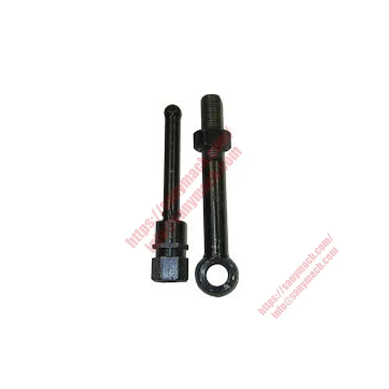
The genuine SANY parts reference 160102130004A101 is the Push Rod, a precision‑engineered tubular component that transfers linear motion from the camshaft tappet to the rocker arm in SANY overhead‑valve heavy‑duty diesel engines. This push rod converts the upward movement of the tappet into force that opens the intake or exhaust valve, playing a critical role in engine breathing and combustion efficiency.
The 160102130004A101 push rod is manufactured from high‑strength cold‑drawn steel tubing with induction‑hardened ends, delivering exceptional column strength, lightweight construction, and resistance to bending under high spring loads. Each 160102130004A101 unit is 100% inspected for straightness, length, and end hardness, guaranteeing reliable valve actuation in SRT dump trucks, SY excavators, SW wheel loaders, and motor graders.
As an essential link in the SANY Valve Train Group, the 160102130004A101 Push Rod works in concert with the Camshaft, Tappet, Rocker Arm, Valve Bridge, and Valve Spring. When the camshaft lobe lifts the tappet, the push rod transfers this motion upward, causing the rocker arm to pivot and push the valve open. The push rod must be both stiff enough to transmit force without buckling and light enough to follow the cam profile at high engine speeds.
The 160102130004A101 push rod features spherical ends that fit into the tappet socket and rocker arm socket, allowing for angular misalignment while maintaining positive contact. Each 160102130004A101 unit is 100% inspected for length accuracy, end hardness, and straightness, guaranteeing reliable performance in the most demanding mining, construction, and material handling environments.
Material and Design of Push Rod 160102130004A101
The push rod 160102130004A101 is manufactured from cold‑drawn seamless steel tubing, typically made from SAE 1018 or 1020 low‑carbon steel. The tube is drawn to precise outer diameter (typically 8‑10 mm) and wall thickness (1.5‑2.0 mm) to achieve the optimal balance between column strength and weight. The hollow construction reduces reciprocating mass, allowing the valve train to follow the cam profile accurately at high engine speeds. The material is normalized to relieve internal stresses and improve dimensional stability.
The ends of the 160102130004A101 push rod are induction‑hardened to achieve a surface hardness of 45‑55 HRC to a depth of 0.5‑1.0 mm, while the core remains ductile (25‑35 HRC). The ends are formed into spherical balls that seat into the tappet socket and rocker arm socket. The spherical profile (typical radius 6‑8 mm) allows the push rod to pivot slightly as the rocker arm rotates, accommodating angular misalignment without binding. The ball ends are polished to a surface finish of Ra ≤ 0.8 µm to reduce friction and wear.
The overall length of the 160102130004A101 push rod is engine‑specific, ranging from 150 to 250 mm, with a tolerance of ±0.2 mm. The length must be exact to set the correct valve clearance (lash) when used with adjustable rocker arms. Straightness is critical – the maximum allowable bow is 0.1 mm per 300 mm length. Bent push rods can cause rocker arm misalignment, uneven valve motion, and premature wear. All push rods are 100% inspected for straightness using a dial indicator and V‑blocks.
A light phosphate or zinc coating is applied to the 160102130004A101 push rod to protect against corrosion during storage. The tube may be painted or left natural with an oil film. A batch code is stamped on the push rod end or printed on the packaging, providing full traceability to the tube lot, heat treat parameters, and final inspection records.
Integration Within the SANY Valve Train Group
The push rod 160102130004A101 is a critical link in the overhead‑valve (OHV) configuration used in many SANY diesel engines. The valve train sequence is: crankshaft → timing gears → camshaft → tappet (lifter) → push rod → rocker arm → valve bridge (for 4‑valve heads) → valve stem. The camshaft lobe pushes the tappet upward. The tappet, in turn, pushes the push rod. The push rod transfers the motion to the rocker arm, which pivots on its shaft and pushes the valve open.
During the valve closing phase, the valve spring pushes the rocker arm back, which pushes the push rod down, which pushes the tappet down to follow the camshaft base circle. The push rod must therefore be strong enough to transmit compressive force without buckling (Euler column) and also to resist tensile forces from spring rebound. The hollow tube design provides a high strength‑to‑weight ratio.
All push rods in an engine must be of identical length and weight to ensure consistent valve lash and balanced engine operation. The 160102130004A101 push rods are supplied as matched sets (12 pieces for a 6‑cylinder engine with 4 valves per cylinder, or 6 pieces for a 2‑valve per cylinder design). Using genuine SANY push rods guarantees correct length, straightness, and end hardness for the specific engine model.
Machine Compatibility & Critical Applications
The push rod 160102130004A101 is used in SANY D09 and D12 series diesel engines powering a wide range of heavy‑duty SANY equipment. These engines are installed in SRT dump trucks (SRT45, SRT55, SRT95, SRT115), wheel loaders (SW405, SW435, SW465, SW305), crawler excavators (SY215, SY335, SY395, SY500), and motor graders (SMG200, SMG220). It is also installed on SANY concrete pump trucks, crawler cranes, and heavy forklifts.
The D09 engine is a straight‑6 diesel with 8.7 liters displacement, 117 mm bore, 135 mm stroke, producing 280‑380 HP and 1,500 N·m of torque. The D12 engine offers 12.13 liters displacement, 131 mm bore, 150 mm stroke, with torque reaching 700 N·m. Both engines utilize SANY’s patented TOP‑Down cooling system and split‑type cylinder head. The push rod must operate reliably at engine speeds up to 2,100 rpm, experiencing millions of compression cycles over the engine’s life.
For complete valve train reliability, the 160102130004A101 push rod must be used together with genuine SANY tappets, rocker arms, and valve bridges. When overhauling an engine, always replace push rods as a set – never mix old and new push rods, as length variations can cause uneven valve lash. Use genuine SANY push rods to ensure correct material, straightness, and end hardness.
Technical Specifications – Push Rod 160102130004A101
| Parameter | Specification / Value |
|---|---|
| OEM Part Number | 160102130004A101 |
| Product Name | Push Rod / Engine Push Rod / Valve Lifter Rod |
| Material | Cold‑drawn seamless steel tube (SAE 1018 / 1020) |
| Outer Diameter (mm) | 8 – 10 mm (engine‑specific) |
| Wall Thickness (mm) | 1.5 – 2.0 mm |
| Overall Length (mm) | 150 – 250 mm (±0.2 mm) |
| End Hardness | 45 – 55 HRC (induction hardened) |
| Core Hardness | 25 – 35 HRC |
| Spherical Ball Radius (mm) | 6 – 8 mm (engine‑specific) |
| Straightness Tolerance | ≤ 0.1 mm per 300 mm length |
| Surface Finish (Ends) | Ra ≤ 0.8 µm |
| Surface Treatment | Phosphate or zinc coating + anti‑rust oil |
| Quantity per 6‑Cylinder Engine | 12 (for 4‑valve/cyl) or 6 (for 2‑valve/cyl) |
Proper Installation of Push Rod 160102130004A101
When installing the push rod 160102130004A101, begin by inspecting each push rod for straightness. Roll the push rod on a flat surface – any wobble indicates a bent rod that must be rejected. Clean the push rod ends and the tappet and rocker arm sockets thoroughly. Lubricate the ball ends with engine assembly lube or clean engine oil. Insert the push rod through the cylinder head passage (in overhead‑valve designs), seating the lower ball into the tappet socket and the upper ball into the rocker arm socket.
Ensure that the push rod is not contacting the push rod passage wall – there should be a small clearance to prevent rubbing. After all push rods are installed, adjust the valve lash (clearance) according to the SANY workshop manual procedure. Turn the engine to bring each cylinder to top dead center on the compression stroke, then loosen the rocker arm adjustment screw, insert a feeler gauge (typically 0.2‑0.4 mm for intake, 0.4‑0.6 mm for exhaust), and tighten the locknut while holding the adjustment screw.
Never overtighten the rocker arm adjustment screw – this will preload the push rod and keep the valve slightly open, causing loss of compression and possible valve burning. If a push rod is bent or has a worn ball end, replace it immediately. Always replace push rods as a complete set when installing a new camshaft or new tappets, as wear patterns may not match.
After installation, rotate the engine by hand two full revolutions and recheck valve lash. If the engine has hydraulic tappets, no lash adjustment is needed – simply ensure the push rods are seated and the tappets are pumped up with oil before starting. Store new push rods in a clean, dry place, protected from bending.
Symptoms of a Damaged Push Rod
A bent or worn push rod 160102130004A101 can cause several engine problems. A persistent clicking or tapping noise from the valve cover that does not go away after warm‑up often indicates excessive valve lash due to a bent push rod or worn ends. If the push rod is bent, the rocker arm cannot maintain proper contact, causing a clicking sound at each valve opening. Loss of power and rough idle may occur if the valve does not open fully due to reduced effective length of a bent push rod.
If a push rod breaks completely, the valve will not open at all, causing that cylinder to misfire, producing a dead cylinder condition. The engine will run poorly with a noticeable miss, and unburned fuel may exit the exhaust. A compression test will show zero or very low compression in the affected cylinder. Broken push rods are often caused by valve‑to‑piston contact (due to incorrect timing or a jumped timing chain/belt) or by excessive valve spring force.
During engine disassembly, inspect each push rod for straightness by rolling on a flat surface. If the ball ends are scored or flattened, replace the push rod. If any push rod is bent or worn, replace the entire set, as other push rods may have unseen stress damage. Always use genuine SANY push rods to ensure proper length, hardness, and straightness.
Quality Assurance & Full Traceability
Every push rod 160102130004A101 is manufactured in an IATF 16949 certified facility under SANY’s rigorous quality management system. The production process includes raw material certification, tube drawing inspection, end‑forming dimensional checks, and 100% straightness verification using automated optical or laser systems. A sample from each batch is sectioned for metallographic examination to verify case depth and microstructure.
The induction hardening process is monitored for consistent temperature and depth. Each push rod is measured for overall length with a precision gauge (±0.05 mm). The ball ends are inspected for radius and surface finish. Straightness is verified using a dial indicator and V‑blocks; any rod exceeding the 0.1 mm per 300 mm limit is rejected. A batch code is stamped on the push rod or printed on the packaging, providing full traceability to the tube lot, heat treat data, and final inspection records.
For bulk orders, a Certificate of Conformance (CoC) is provided, certifying that the push rods meet all SANY OEM specifications for material, dimensions, hardness, and straightness. Independent third‑party audits ensure continuous compliance with ISO 9001:2015 and IATF 16949 standards.
Field Performance of Genuine SANY Push Rod
Field data from SANY dump trucks and excavators operating in Australian iron ore mines and South African quarries shows that genuine 160102130004A101 push rods maintain straightness and end hardness for the full engine service interval, typically exceeding 20,000 operating hours. Aftermarket push rods often fail prematurely due to lower‑quality tubing, inadequate hardening, or poor straightness, leading to bent rods, uneven valve lash, and valvetrain noise within 8,000‑10,000 hours.
The superior durability of the genuine SANY push rod comes from the high‑quality cold‑drawn steel, the precise induction hardening that provides a wear‑resistant surface with a tough core, and the strict straightness control. Fleet owners report that standardizing on genuine SANY push rods eliminates valve train noise and ensures consistent valve lash over long operating intervals.
To maximize service life, always replace push rods when installing a new camshaft or new tappets. Use genuine SANY push rods to ensure correct length and hardness. During engine assembly, verify that each push rod rotates freely when the engine is turned over – rotation indicates that the ball ends are properly seated and the rod is straight. Following these practices ensures reliable valve actuation and long engine life.
Always order using the full part number 160102130004A101 to ensure correct length, hardness, and straightness. Genuine SANY push rods deliver reliable force transmission, wear resistance, and long service life. For complete valve train reliability, install 160102130004A101 together with genuine SANY tappets, rocker arms, and camshafts. Trust only SANY original parts to keep your engine’s valves opening precisely – your equipment depends on it.
Online Catalog of SANY Parts
Learn MoreIf you have any questions about our products, services, or anything related to what we offer, please don’t hesitate to leave us a message—our dedicated team is always ready to provide prompt and helpful responses to address your concerns. What’s more, when you become our valued customer, we’re delighted to offer you complimentary catalog services, giving you access to detailed, up-to-date information on our full range of products, specifications, and offerings to help you make informed decisions.